Viewport and Camera
The viewport or viewport-webgl modules supply an easy way of creating a viewport area and managing the camera controls.
The Viewport
The viewport is the visual area that shows the configurable 3d model. In general a viewport is a box on the web page that has a pixel width and height and that displays the image that is seen by the virtual camera. Setting up the viewport is described in the minimal example section.
The Camera
The camera is the virtual device that is used to see the object. The image of the camera is displayed inside the viewport. The position and orientation of the camera is defined by a set of geometric parameters:
| Element | Type | Description |
| focus | 3-vector | This marks the central position of the virtual lens of the camera. It is the point where all geometric light rays of the final image are bundled and it is therefore the "real" position of the camera. |
| view | 3-vector | Describes the direction the camera looks into. |
| top | 3-vector | Describes the direction to the top of the camera. |
| right | 3-vector | Describes the direction to the right of the camera. |
| aperture | float | This is the angle of view of the camera in either horizontal or vertical direction, measured in degrees. It's in horizontal direction if the viewport's pixel width is smaller than its height and in vertical direction otherwise. |
| origin | 3-vector | Defines the center of rotation the camera moves around when orbiting. This point typically lies within or close to the object examined by the camera. |
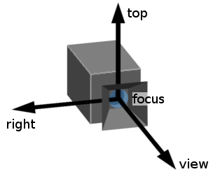
The focus position of the camera and its three directions view, top and right.
The view, top and right vectors are orthogonal on each other.
Camera Movement Modes
The camera can perform a number of movements that are explained in the following sections.
Movement Controls Table
| Movement mode | Mouse Mode Controls | Touch Mode Controls |
| Orbiting | left mouse button | one finger | |
| Dollying | mouse wheel | two fingers (pinch and spread) | |
| Rolling | - | two fingers (rolling) |
| Shifting | right mouse button | - | |
| Panning | [control] + left mouse button | - | |
| Zooming | [control] + mouse wheel | - |
Orbiting
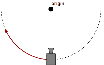
Camera orbiting around the origin.
This camera movement typically appears in a configurator setup where the user examines a model by turning it into various directions (left/right, up/down). This turning corresponds to an orbiting of the camera around the object, if this is imagined to be fixed in space. In fact the camera orbits around the point defined as vector origin in the camera parameters. In paramate, the orbit mode is applied by clicking with the left mouse button and moving the mouse cursor (mouse mode) or by touching with one finger and moving it along the touch surface (touch mode).
The orbit mode itself can come in different versions that define how the camera moves around the object:
- turn-and-flip mode
- turntable mode
- turntable mode (with overturning)
Dollying

If the camera approaches the origin or gets retracted from it, it applies a dollying effect.
Dollying (often confused with zooming) means to approach or retract the camera from the origin point (the term is derieved from the usage of camera dollies in filmmaking). This has the effect of enlarging or shrinking the visual size of an object. It can be applied by moving the mouse wheel (mouse mode) or by a two finger pinch and spread gesture (touch mode).
Shifting
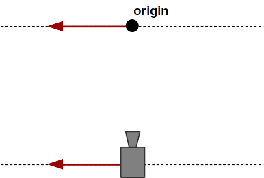
Camera shifting to the left.
The shifting movement moves the camera sideways or up and down without tilting its viewing direction. At the same time, the origin is shifted in parallel with the camera. This ensures that when the camera ends up in a new position, it can orbit around the same point on the viewing screen as before the shifting (what is often the central point). A shifting movement can be carried out in mouse mode by clicking the right mouse button and moving the mouse cursor. It cannot be applied in touch mode.
Panning
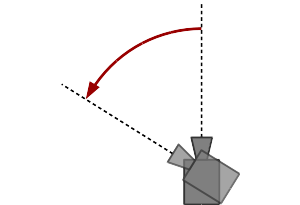
Panning of the camera to the left.
Panning swivells the camera into one direction (left/right or up/down) without changing its position (see https://en.wikipedia.org/wiki/Panning_(camera) ). The origin point used for orbiting is not affected by this operation. The panning mode can be applied by holding the [control] key while using the left mouse button.
Zooming

Zooming-in reduces the angle-of-view of the camera. The opposite effect is zooming-out.
The zooming effect changes the angle of view of the camera while keeping its position unchanged. This results in an enlarging or shrinking of the displayed object while changing the perspective of the image. Note that the term "zoom" is sometimes mistaken for the dolly effect. In paramate mouse mode, zooming can be applied by scrolling on the mouse wheel while pressing the [control] key. It cannot be applied in touch mode.
Automatic Camera Positioning
The automatic camera positioning mechanism is an easy way to ensure that the configured object is properly placed within the camera's view. If this mode is active, the 3d object will always be visible in the center of the viewport and will fit well into it, even if an arbitrary rotation is applied.
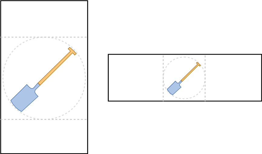
The image shows auto positioning of the camera for viewports with portrait (left) and landscape (right) extensions. The object is always centered and the camera parameters are chosen in a way that the object fits into the viewport under any rotation (dotted circle).
When automatic camera positioning is active, the object stays properly aligned even on changes of the model geometry as it might occur from a configuration. The camera is adjusted automatically after each configuration step.
Automatic camera positioning comes with a couple of limitiations of the degrees of freedom of camera movement. So is it e.g. not possible to shift or pan the camera view away from the object. This implies that any off-centered camera positions require the automatic camera mode to be turned off.
Automatic camera positioning can be activated/deactivated via the viewport constructor or via function setCameraAutoPos .